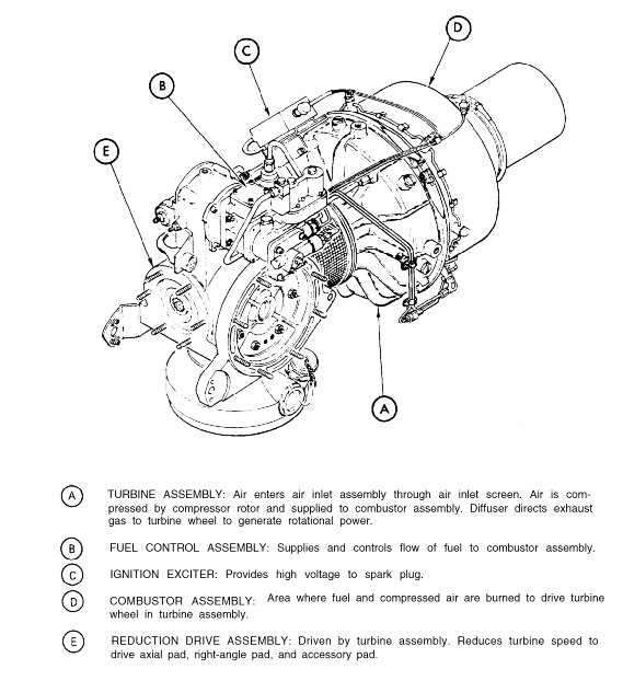
|
| The Auxiliary Power Unit |
|
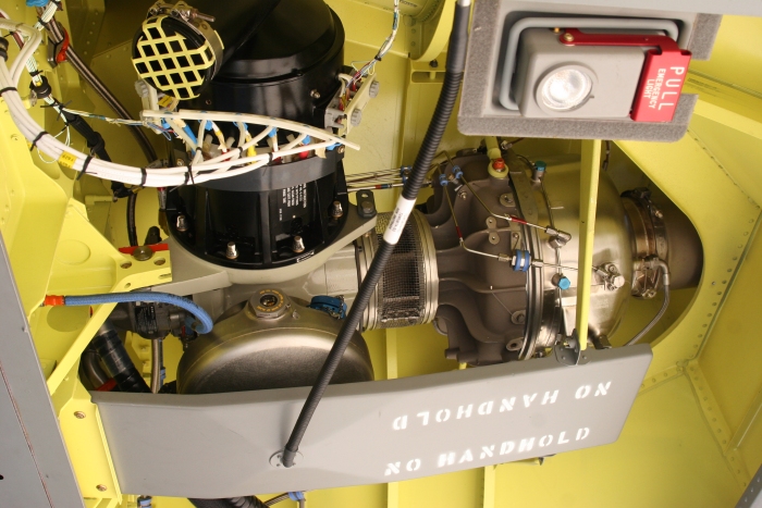
| The Auxiliary Power Unit (APU) installed in CH-47F Chinook 07-08736. Click-N-Go Here to view a larger image. |
|
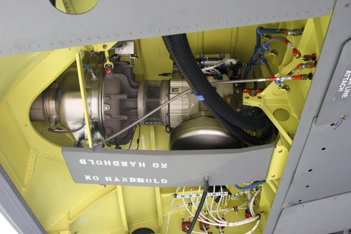
| The Auxiliary Power Unit (APU) installed in CH-47F Chinook 07-08738. Click-N-Go Here to view a larger image. |
|
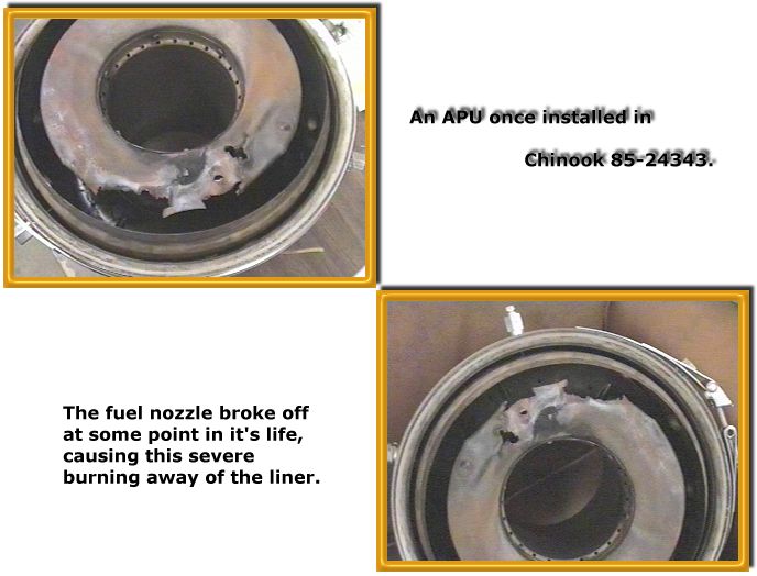
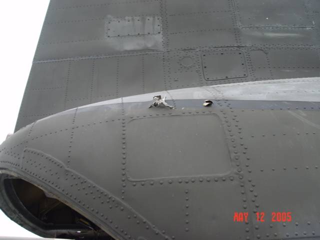
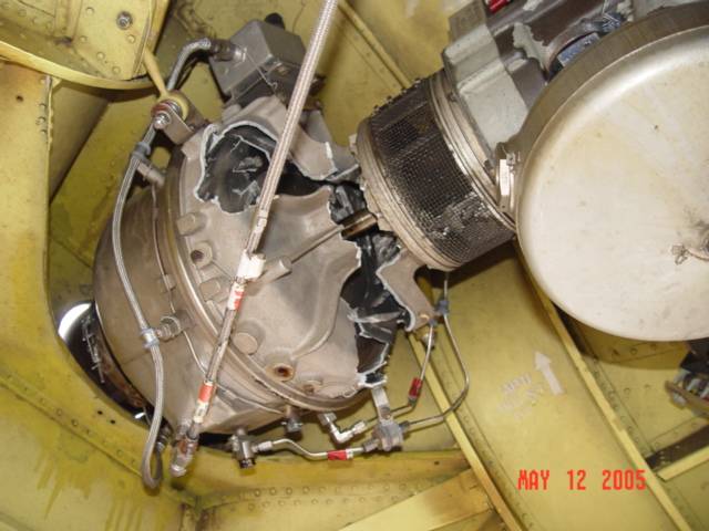
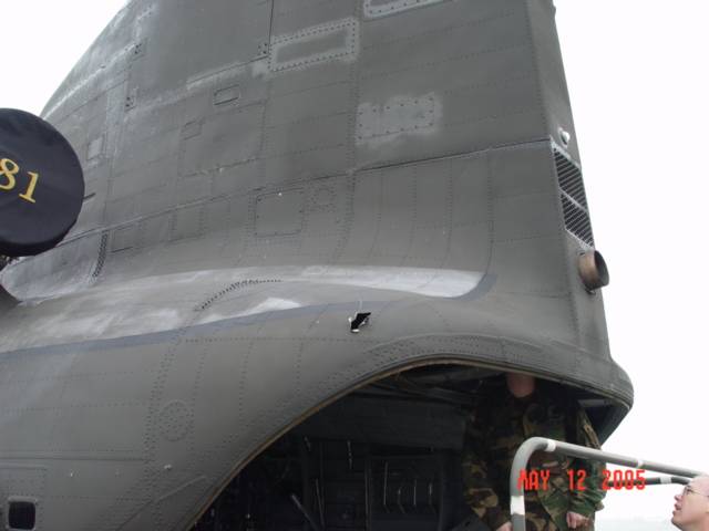
| The Auxiliary Power Unit liner shown above came from CH-47D Chinook 85-24343. The APU had been in service for well over a year. During that time, the APU produced a rather unusual and quite interesting sound - almost a whistle, but nothing to really complain about. As the APU continued to run in a dependable manner, it was left in service. Eventually, after several hundred hours of operation, it just wouldn't start anymore. Once removed from the aircraft and inspected, it was discovered that the fuel nozzle had broke off inside and resulted in a concentrated flame, like a gas torch, striking the wall of the liner. As one can see, it left quite a mark upon the liner. |
|
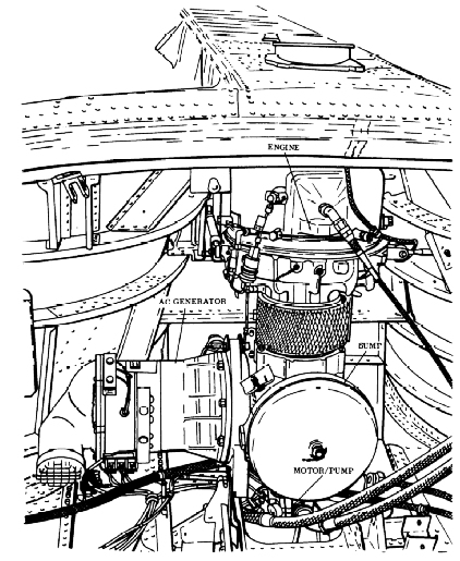
| The gas turbine auxiliary power unit T62-T-2B (APU) is mounted in the aft cabin above the ramp. The basic components of the APU are the gas turbine engine, hydraulic motor-pump, fuel control, accessory drive, and AC generator. An APU Electronic Sequencing Unit (ESU) which monitors APU operation is on the left side of the cabin above the ramp. The ESU monitors APU starting and operation. In addition, it monitors APU speed and exhaust gas temperature. The unit continuously compares these parameters with limits programmed into ESU circuits. If a limit is exceeded, the ESU will automatically shut down the APU. The ESU does not monitor hydraulic motor pump or generator output. The motor-pump on the APU pressurizes the utility and hydraulic system for main engine starting and ground checks. The APU also drives an AC generator (20 KVA) which supplies power to No. 1 and No. 2 electrical systems. The APU oil supply is integral and contained within the sump of the accessory drive assembly. The APU receives fuel from the left main fuel tank through a booster pump, a manual fuel shutoff valve, and a solenoid valve. |
| The use of the T62-T-2B APU began with the production of the CH-47D and E and continued on with the production of the F and G model Chinook helicopters. |
|
| Weight (including residual fluids).............74.8 lb(16.5 kg) | |
| Length..........................................................33 in. (82 cm) | |
| Width...........................................................14 in. (36 cm) | |
| Height..........................................................24 in. (60 cm) | |
| Lubricating Oils.........................................MIL-L-23699 | |
| MIL-L-7808 | |
| Oil Sump Capacity (max)...........................3 US quart (2.8 L) |
| When the Turbine Wheel Fails |
| In the Pilot's Checklist it states: "APU - Clear." |
| Below are photographs showing what happens when a compressor turbine wheel fails in the APU. It is a good example of why no personnel should be in the vicinity of any turbine engine during the start sequence. One would not want to be standing in the way of these razor blades. |
|
|
|
|
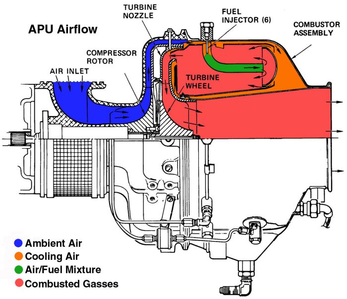
| The APU Air Flow during operation. Click-N-Go Here to view a larger image. |
|
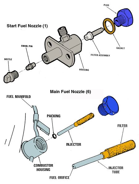
| The APU Fuel Nozzles. Click-N-Go Here to view a larger image. |
|
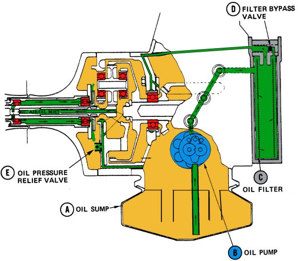
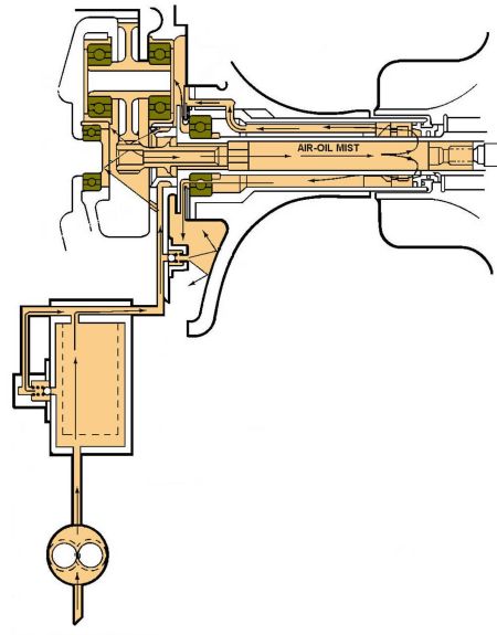
| The APU Oil Flow during operation. Click-N-Go Here to view a larger image. |
|
| The APU Oil Flow during operation. Click-N-Go Here to view a larger image. |
|
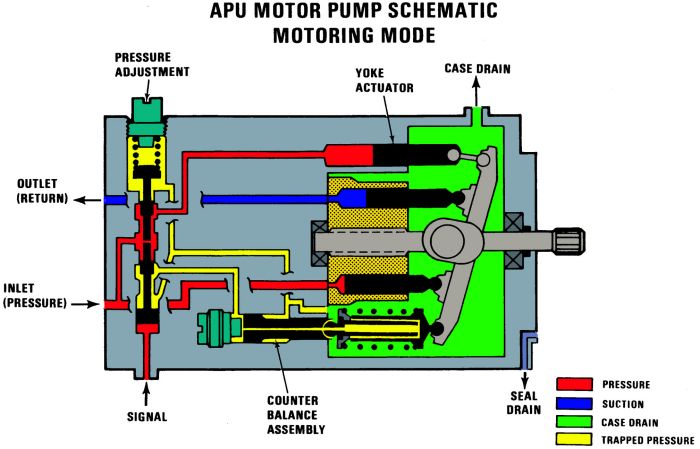
| The APU Motor Pump in the motoring mode. Click-N-Go Here to view a larger image. |
|
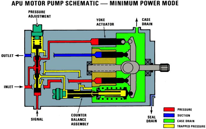
| The APU Motor Pump in the minimum power (pumping) mode. Click-N-Go Here to view a larger image. |
|
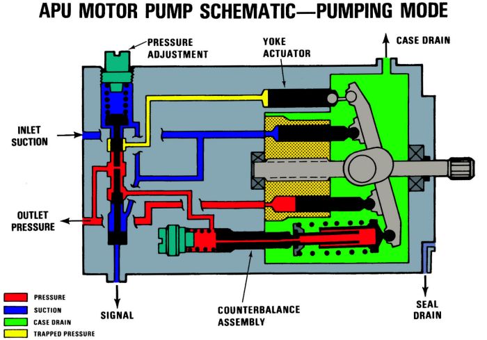
| The APU Motor Pump in the pumping mode. Click-N-Go Here to view a larger image. |
|
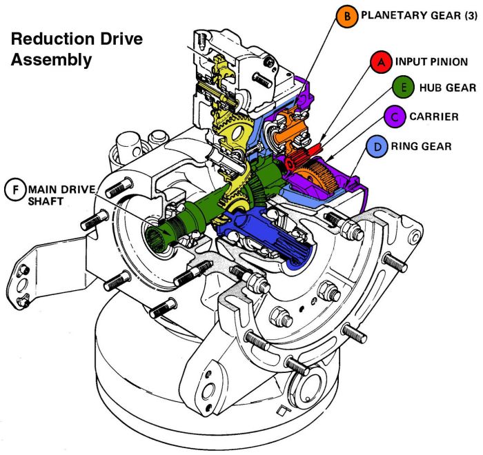
| The APU Reduction Drive Assembly. Click-N-Go Here to view a larger image. |
|
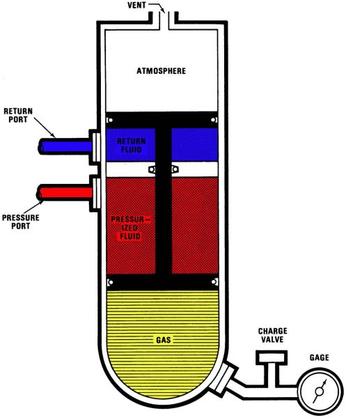
| The APU Start Accumulator (375 cubic inch). Click-N-Go Here to view a larger image. |
|
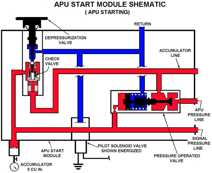
| The APU Start Module in the APU Starting Mode. Click-N-Go Here to view a larger image. |
|
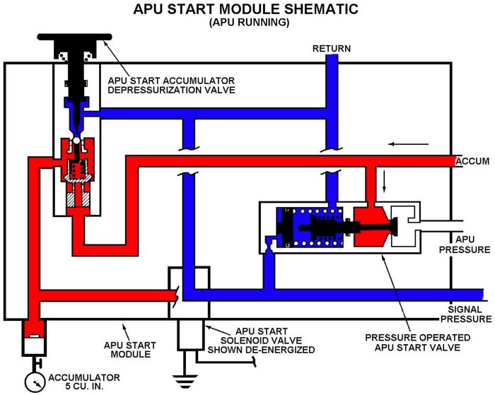
| The APU Start Module in the APU Running Mode. Click-N-Go Here to view a larger image. |
 |
|
| Comments or Questions ? |  |
Email the Webmaster. |
|
|